
Power factor basics:
Power quality is essential for efficient equipment operation, and power factor contributes to this.
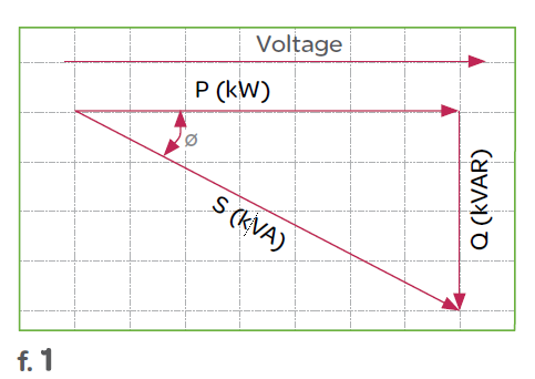
Power factor is the measure of how efficiently incoming power is used in an electrical installation. It is the ratio of active to apparent power, when:
The power triangle:

Poor power factor (for example, less than 95%) results in more current being required for the same amount of work.
Power factor correction
Power factor correction (PFC) aims to improve power factor, and therefore power quality. It reduces the load on the electrical distribution system, increases energy efficiency and reduces electricity costs. It also decreases the likelihood of instability and failure of equipment.
Power factor correction is obtained via the connection of capacitors which produce reactive energy in opposition to the energy absorbed by loads such as motors, locally close to the load. This improves the power factor from the point where the reactive power source is connected, preventing the unnecessary circulation of current in the network.


Determining the PFC required
The selection of PFC equipment should be done according to the following four-step process, by persons with the relevant skills:
Step 1: Calculation of the required reactive power
The objective is to determine the required reactive power (Qc (kvar)) to be installed, in order to improve the power factor (cos φ) and reduce the apparent power (S).

Qc can be determined from the formula Qc = P (tan φ – tan φ‘), which is deduced from the diagram.
The parameters φ and tan φ can be obtained from billing data, or from direct measurement in the installation.
Step 2: Selection of the compensation mode
The location of low-voltage capacitors in an installation can either be central (one location for the entire installation), by sector (section-by-section), at load level, or a combination of the latter two.

In principle, the ideal compensation is applied at a point of consumption and at the level required at any moment in time. In practice, technical and economic factors govern the choice.
The location is determined by:
Step 3: Selection of the compensation type
Different types of compensation should be adopted depending on the performance requirements and complexity of control:
Step 4: Allowance for operating conditions and harmonics
Operating conditions have a great impact on the life expectancy of capacitors, so the following parameters should be taken into account:
Some loads (variable speed motors, static converters, welding machines, arc furnaces, fluorescent lamps, etc.) pollute the electrical network by reinjecting harmonics. It is therefore also necessary to consider the effects of these harmonics on the capacitors.
The benefits of power factor correction
Savings on the electricity bill
Power factor correction eliminates penalties on reactive energy, decreases demand on kVA, and reduces power losses generated in the transformers and conductors of the installation.
Increased available power
Fitting PFC equipment on the low voltage side increases the power available at the secondary of a MV/LV transformer. A high power factor optimises an electrical installation by allowing better use of the components.
Reduced installation size
Installing PFC equipment allows conductor cross-section to be reduced, as less current is absorbed by the compensated installation for the same active power.
Reduced voltage drops
Installing capacitors allows voltage drops to be reduced upstream of the point where the PFC device is connected, therefore preventing overloading of the network and reducing harmonics.