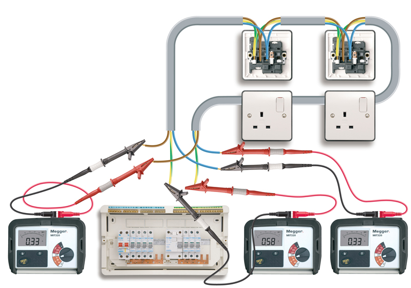
This diagram from Megger will walk through the process of checking the continuity of live protective conductors for compliance with Regulation 612.2.2.
- Ensure installation, or appropriate part of it, is securely isolated, and proved to be so, before proceeding.
- Measure resistance of each loop in turn of phase, neutral and circuit protective conductors and record measured data, r1, rn and r2 respectively.
- Where the CPC is the same cross-sectional area as the live conductors, the resistance values for the three conductors should be the same (within 50 mW).
- Where the CPC is 1.5 mm2 and the live conductors are 2.5 mm2, the measured value of the CPC should be 1.67 times that of the live conductors.
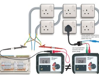
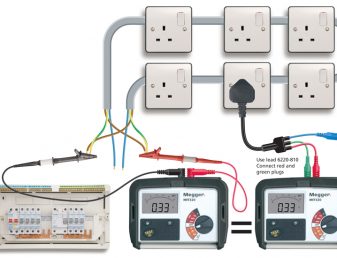
The next diagram from Megger shows how you can check the continuity of ring final circuit conductors.